PLUNGER CONTROL VALVE, DUCTILE IRON, PN25
SS trim/piston, bronze guides, A4/A2 bolts, Rotork gearbox, modulating, 250µm blue RAL5017 EP

Contact
AVK Valves Korea Co., Ltd.
Suite 1409, 14/F, CENTUM LEADERS MARK, 17, APEC-ro, Haeundae-gu, Busan 48060, Korea
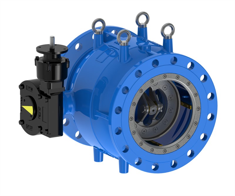
Plunger control valve for flow rate control and pressure reducing applications. For water and other neutral and hydrocarbon-free media to max. 70°C.
AVK series 870 are designed as plunger control valves for inline applications. Unlike butterfly- or gate valves, that should only be in either fully open or fully closed position, plunger valves are designed to operate in between and perform control functions in water supply systems.
The design consists of a single-piece body made of epoxy coated ductile iron. Internal components in contact with water are made of either stainless steel or bronze; materials that guarantee a good anti-corrosion performance and a long service life.
| Variant 870/0007-002 | |
|---|---|
| Connection: | Flanged |
| Material: | Ductile iron |
| DN: | DN200 - DN600 |
| PN: | PN 25 |
Features
- One-piece body construction
- T-shape main seal located in safety flow area ensuring minimal wear and long service life
- Maintenance access is conveniently provided by the downstream retaining ring and the upstream cover being attached with screws
- Low operating torque due to pressure balance in chamber inside
- Gearbox suitable for modulating operation
- Low head loss coefficient in fully open position due to optimized internal body shape
- Double O-ring sealed drive shaft with all other shafts and bearings protected against corrosion with O-ring combinations
- 4 guide rails ensure no vibration during operation and accurate alignment throughout full valve stroke
- Body in ductile iron with internal parts in stainless steel and bronze guide rails for high corrosion resistance
- Internally and externally corrosion protected with a coating of blue RAL 5017 fusion bonded epoxy to DIN 3476 and applied in a GSK approved process.
Downloads
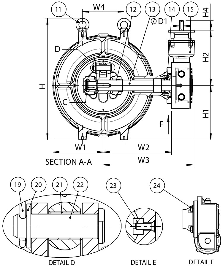
Reference nos. and dimensions:
| Reference no. | DN mm |
Flange drilling |
L mm |
L1 mm |
H mm |
H1 mm |
H2 mm |
H4 mm |
W1 mm |
W2 mm |
W3 mm |
W4 mm |
D1 mm |
Theoretical weight/kg |
|---|---|---|---|---|---|---|---|---|---|---|---|---|---|---|
| 870-0200-00-746407 | 200 | PN25 | 400 | 140 | 433 | 190 | 122 | 51 | 180 | 225 | 328 | 140 | 20 | 95 |
| 870-0250-00-746407 | 250 | PN25 | 450 | 230 | 503 | 225 | 263 | 51 | 213 | 300 | 403 | 230 | 20 | 163 |
| 870-0300-00-746407 | 300 | PN25 | 500 | 200 | 584 | 261 | 263 | 51 | 243 | 328 | 431 | 200 | 20 | 218 |
| 870-0350-00-746407 | 350 | PN25 | 550 | 200 | 664 | 301 | 291 | 51 | 278 | 370 | 476 | 240 | 20 | 296 |
| 870-0400-00-746407 | 400 | PN25 | 600 | 240 | 755 | 342 | 313 | 51 | 323 | 430 | 562 | 300 | 20 | 429 |
| 870-0450-00-746407 | 450 | PN25 | 650 | 340 | 811 | 370 | 335 | 51 | 349 | 460 | 592 | 340 | 20 | 556 |
| 870-0500-00-746407 | 500 | PN25 | 700 | 340 | 884 | 397 | 335 | 51 | 379 | 490 | 622 | 340 | 20 | 648 |
| 870-0600-00-746407 | 600 | PN25 | 800 | 400 | 1050 | 480 | 335 | 51 | 441 | 560 | 692 | 500 | 20 | 1016 |
Components
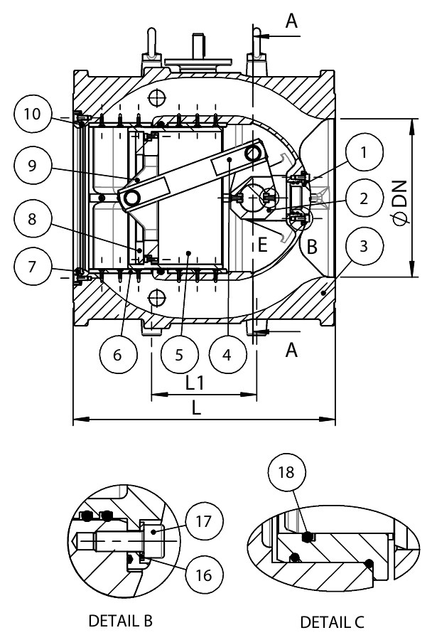
| 1. | Upstream cover | Stainless steel, cast |
| 2. | Crank | Stainless steel 1.4308 (CF8), cast |
| 3. | Body | Ductile iron GJS-500-7 (GGG-50) |
| 4. | Push rod | Stainless steel |
| 5. | Piston | Stainless steel |
| 6. | Guide rail | Bronze CC499K |
| 7. | Retainer ring | Stainless steel |
| 8. | Lock ring | Stainless steel |
| 9. | Piston flange | Stainless steel 1.4308 (CF8), cast |
| 10. | Main seal | EPDM rubber |
| 11. | Lifting eye | Stainless steel A4 |
| 12. | Bush | Bronze CC499K |
| 13. | Shaft, drive | Stainless steel 1.4021 |
| 14. | Seal housing | Bronze CC499K |
| 15. | Gearbox | Ductile Iron |
| 16. | Washer | Bronze CC499K |
| 17. | Bolt | Stainless steel A4 |
| 18. | O-ring | EPDM rubber |
| 19. | Split pin | Stainless steel A4 |
| 20. | Washer | Stainless steel A4 |
| 21. | Bush | Bronze CC499K |
| 22. | Clevis pin | Stainless steel A4 |
| 23. | Key | Stainless steel A4 |
| 24. | Bolt | Stainless steel A2 |
Test/Approvals
- Hydraulic test according to EN 1074-1 and 5, EN12266 |
- Seat: 1.1×PN (in bar), Body: 1.5×PN (in bar).
Standards
- Face-to-face dimension according to EN 558, basic series 15
- Flange drilling to EN1092, PN25
- Designed according to EN 1074-1/5 & EN1349